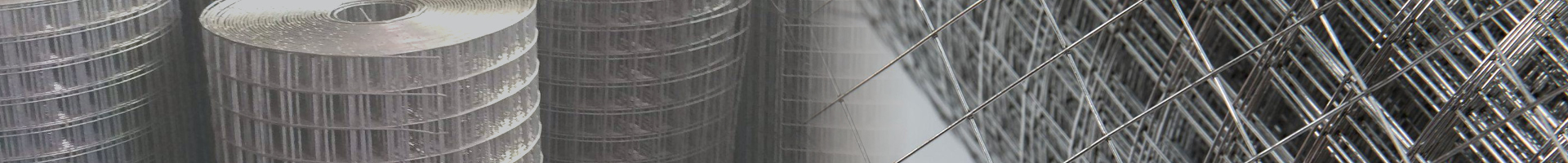
We supply chain link mesh fabric, posts, rails, barbed wire and / or razor wire, gates, and accessories for building airport fencing systems.
Typical chain link Airport Fencing
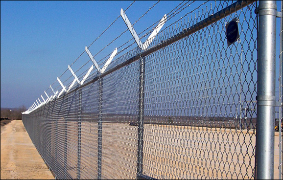
Hot dipped galvanized mesh chain link fence system for airport, with Y post supported barbed wire and optional razor barbed wire topping
SECURITY FENCE GENERAL INFORMATION
Supply of security fence includes materials, installation, testing, grading,
compacting and all work incidental to the completed system.
Supply and
installation of all the posts, rails, braces, electrical grounds, detterent mesh barriers,
tension wires and ties are incidental to the installation of the fence.
Installation of the concertina razor wire is also incidental to the
installation of the fence.
FABRIC. The fabric is woven with a 9-gauge galvanized steel wire in a 2-inch (50 mm) mesh and shall meet the requirements of ASTM A 392, Class 2.
RAZOR WIRE. Concertina razor wire shall be 2-strand 12-1/2 gauge zinc-coated wire with razor barbs wire and shall conform to the requirements of ASTM A 121, Class 3, Chain Link Fence Grade.
POSTS, RAILS AND BRACES. Line posts, rails, and braces shall conform to
the requirements of ASTM F-1043 or ASTM F 1083 as follows:
i. Galvanized tubular steel pipe shall conform to the requirements of Group
IA, (Schedule 40) coatings conforming to Type A, or Group IC (High
Strength Pipe), External coating Type B, and internal coating Type B or
D.
ii. Posts, rails, and braces furnished for use in conjunction with aluminum
alloy fabric shall be aluminum alloy or composite.
iii. Posts, rails, and braces, with the exception of galvanized steel conforming
to F 1043 or ASTM F 1083, Group 1A, Type A, or aluminum alloy, shall
demonstrate the ability to withstand testing in salt spray in accordance
with ASTM B 117 as follows:
i. External: 1,000 hours with a maximum of 5% red
rust.
ii. Internal: 650 hours with a maximum of 5% red
rust.
WIRE TIES AND TENSION WIRES. Wire ties for use in conjunction with a given type of fabric shall be of the same material and coating weight identified with the fabric type. Top and bottom tension wire shall be 7-gauge marcelled steel wire with the same coating as the fabric type and shall conform to ASTM A 824.
MISCELLANEOUS FITTINGS AND HARDWARE. Miscellaneous steel fittings and hardware for use with zinc-coated steel fabric shall be of commercial grade steel or better quality, wrought or cast as appropriate to the article, and sufficient in strength to provide a balanced design when used in conjunction with fabric posts, and wires of the quality specified herein. All steel fittings and hardware shall be protected with a zinc coating applied in conformance with ASTM A 153. Razor barbed wire support arms shall withstand a load of 250 pounds (113 kg) applied vertically to the outermost end of the arm.
MARKING. Each mesh roll carries a tag showing the kind of base metal (steel, aluminum, or aluminum alloy number), kind of coating, the gauge of the wire, the length of fencing in the roll, and the name of the manufacturer. Posts, wire, and other fittings are identified as to manufacturer, kind of base metal (steel, aluminum, or aluminum alloy number), and kind of coating.
PHYSICAL REQUIREMENTS OF THE FENCE BARRIERS
Concrete Finishing - a finish
comparable to the steel form finish and be uniform for all sections.
Steel Reinforcement - Assembled as a cage with sufficient steel mat and bar to
maintain shape during casting.
Strength Properties - Reinforcing steel bar cylinders tested in accordance with ASTM C39.
LIST OF SUPPLY
Manufacturer's Catalog Data
Chain-Link Fencing Components
Accessories
Gate Operator
Certificates of Compliance
Wire Mesh Fabric
Steel Posts
Braces
Framing
Rails
Tension Wires
EXECUTION
CLEARING FENCE LINE. All trees, brush, stumps, logs, and other debris
which would interfere with the proper construction of the fence in the required
location shall be removed a minimum width of 500mm on each side of the fence
centerline before starting fencing operations.
INSTALLING POSTS. All posts shall be set on the concrete barriers at the
required dimension and depth and shall be spaced not more than 3m apart and
should be set a minimum of 400 mm in the concrete barrier. The posts holes shall
be in proper alignment so that there is a minimum of 75 mm of concrete on all sides of the posts. The posts may be welded to a galvanized plate to be bolted on
the concrete barrier.
All posts shall be set plumb and to the
required grade and alignment.
After the posts are set, the remainder of the drilled hole shall be filled with grout.
INSTALLING BRACES. Horizontal brace rails, with diagonal truss rods and turnbuckles, are installed at all terminal posts or the fence alignment changes more than 30 degrees.
INSTALLING WIRE CLOTH FABRIC. The wire fabric shall be firmly attached to the posts and braced in the manner shown on the plans. All wire shall be stretched taut and shall be installed to the required elevations. The fence shall generally follow the contour of the ground, with the bottom of the fence fabric no less than 25 mm or more than 100 mm from the top of the concrete barrier. Grading shall be performed where necessary to provide a neat appearance.
ELECTRICAL GROUNDS. Electrical grounds shall be constructed where a power line passes over the fence and at 500-foot (150 m) intervals. The ground shall be installed directly below the point of crossing of the power line. The ground shall be accomplished with a copper clad rod 3 metres long and a minimum of 20 mm in diameter driven vertically until the top is 150 mm below the ground surface. A No. 6 solid copper conductor shall be clamped to the rod and to the fence in such a manner that each element of the fence is grounded. Installation of ground rods shall not constitute a pay item and shall be considered incidental to fence construction.
Material Certification
Submit manufacturer's test data and certification. Include stamped, signed, and dated manufacturer's drawings,
information and etc.
Indicate electric power requirements, sensing [loop and lead-in wire] installation
details, wiring diagrams.
Markings and designs of messages on signs and notices.
Product Data
Provide detailed diagrams of all gate components.
Installation instructions.
Drive unit shall bear a label indicating that the operator mechanism has been tested to CSA standards for all electrical components.
SUPPLY LIST OF SLINDING GATES, CANTILEVERED GATES, SWING GATES AND PEDESTRIAN GATES
Single, Double, and Motorized Sliding Gates are measured per each
for the various opening lengths and based on the additional number
authorized by the Airport Authority.
Supply of sliding gates shall include materials,
installation, testing, grading, compacting and all work incidental to the
completed installation of a Sliding Gate.
Also include the
replacement of the existing motors and the reconnection of all the
electronic equipment currently controlling or monitoring the gate.
Supply
and installation of all the posts, rails, braces, electrical grounds, tension
wires and ties shall be incidental to the installation of the gate. Installation
of three razor wire strands, the photocell, and the vehicle detection loops
shall also be incidental to the installation of the gates.
Single, or Double Cantilevered Gates are measured per each for the
various opening lengths and based on the additional number authorized by
the Airport Authority.
Supply of cantilevered gates shall include materials, installation,
testing, grading, compacting and all work incidental to the completed
installation of a Cantilevered Gate.
Replacement of the existing motors and the reconnection of all the
electronic equipment currently controlling or monitoring the gate.
Supply
and installation of all the posts, rails, braces, electrical grounds, tension
wires and ties shall be incidental to the installation of the gate.
Installation
of three razor wire strands, the photocell, and the vehicle detection loops
shall also be incidental to the installation of the gates.
Single or Double Swing Gates are measured per each for the various
opening lengths and based on the additional number authorized by the
Airport Authority.
Supply of swing gates shall include materials, installation, testing,
grading, compacting and all work incidental to the completed installation
of a Swing Gate.
Reconnection of all the
electronic equipment controlling or monitoring the gate is also included.
Supply
and installation of all the posts, rails, braces, electrical grounds, tension
wires and ties shall be incidental to the installation of the gate.
Installation
of three razor wire strands shall also be incidental to the installation of the
gates.
Pedestrian Gates are measured per each for the various opening
lengths and based on the additional number authorized by the Airport
Authority.
Supply of pedestrian access gates shall include materials, installation, testing, grading,
compacting and all work incidental to the completed installation of a
Pedestrian Gate.
Reconnection of all the
electronic equipment currently controlling or monitoring the gate is included.
Supply
and installation of all the posts, rails, braces, electrical grounds, tension
wires and ties shall be incidental to the installation of the gate.
Installation
of three razor wire strands shall also be incidental to the installation of the
gates.
Aluminum Swing Gates will be measured per each for the various opening lengths and based on the additional number authorized by the Airport Authority. This price shall include materials, installation, testing, grading, compacting and all work incidental to the completed installation of an Aluminum Swing Gate. The price shall also include the reconnection of all the electronic equipment currently controlling or monitoring the gate. Supply and installation of all the aluminum posts, rails, braces, electrical grounds, tension wires and ties shall be incidental to the installation of the gate. Installation of three razor wire strands shall also be incidental to the installation of the gates.
GATES PRODUCTS MATERIALS
FABRIC. The fabric is woven with a 9-gauge galvanized steel wire in a
2-inch (50 mm) mesh and shall meet the requirements of ASTM A 392, Class 2.
RAZOR WIRE. Concertina razor wire shall be 2-strand 12-1/2 gauge zinc-coated wire with razor barbs wire and shall conform to the requirements of ASTM A 121, Class 3, Chain Link Fence Grade.
GATE POSTS, RAILS AND BRACES. Gate posts, rails, and braces shall conform to the requirements of ASTM F-1043 or ASTM F 1083 as follows:
Galvanized tubular steel pipe shall conform to the requirements of Group IA, (Schedule 40) coatings conforming to Type A, or Group IC (High Strength Pipe), External coating Type B, and internal coating Type B or D.
Gate Posts, rails, and braces furnished for use in conjunction with aluminum alloy fabric shall be aluminum alloy or composite.
Posts, rails, and braces, with the exception of galvanized steel conforming to F 1043 or ASTM F 1083, Group 1A, Type A, or aluminum alloy, shall demonstrate the ability to withstand testing in salt spray in accordance with ASTM B 117
WIRE TIES AND TENSION WIRES. Wire ties for use in conjunction with a given type of fabric shall be of the same material and coating weight identified with the fabric type. Top and bottom tension wire shall be 7-gauge marcelled steel wire with the same coating as the fabric type and shall conform to ASTM A 824.
MISCELLANEOUS FITTINGS AND HARDWARE. Miscellaneous steel fittings and hardware for use with zinc-coated steel fabric shall be of commercial grade steel or better quality, wrought or cast as appropriate to the article, and sufficient in strength to provide a balanced design when used in conjunction with fabric posts, and wires of the quality specified herein. All steel fittings and hardware shall be protected with a zinc coating applied in conformance with ASTM A 153. Razor barbed wire support arms shall withstand a load of 250 pounds (113 kg) applied vertically to the outermost end of the arm.
MARKING. Each roll of fabric shall carry a tag showing the kind of base metal (steel, aluminum, or aluminum alloy number), kind of coating, the gauge of the wire, the length of fencing in the roll, and the name of the manufacturer. Posts, wire, and other fittings shall be identified as to manufacturer, kind of base metal (steel, aluminum, or aluminum alloy number), and kind of coating.
Galvanizing to DIN 50976 - Hot-Dip Batch Galvanizing.
Cross-sectional dimensions shall not vary from gate design by more than 6 mm.
Vertical centerline shall not be out of plumb by more than 6 mm.
Longitudinal dimensions shall not vary from design by more than 6 mm in 3 m of
gate opening.
PHYSICAL REQUIREMENTS OF THE CANTILEVERED GATES
Modular cantilevered vehicular access gate for closure of access routes and
regulation of traffic flow.
Modular lightweight construction with tensioned gate design.
Low-resonance operation through guide wheels mounted on structural portals.
Microprocessor electronic control using single-phase 240V power supply.
Standard and optional colour combinations available.
Access control:
Operation: Activated by vehicle detector unit with sensing loop, magnetic
Card, manual key switch, electronic key, pushbutton, or hand-held transmitter.
Attention Devices:
1. Traffic lights
2. Flashing lights
3. Audible warning signals.
COMPONENTS OF THE MODULAR CANTILEVERED GATE
Gate: Modular design, welded portals (posts).
Single or Double gate: 3300 mm high.
Site tensioned extruded aluminum top and bottom beams.
Galvanized tension cables.
26 mm diameter pickets.
Guides:
1. Structural portals with guide wheels and running wheels.
2. Synthetic runners screened by wheel guards.
3. Stop column locking style or slam style with rising plate for snug closure.
4. Post and mounting devices for connection to standard fencing.
Fasteners: Concealed, stainless steel.
Electronic Gate Drive:
Electric microprocessor controller unit, remote pushbuttons, relays and other electrical components: to CSA approval.
Control Unit:
Provide gate control by pushbutton, handheld transmitter, access control card
reader, or any any combination matching the existing opening and monitoring
system.
Limit Switches: Magnetic proximity switch to detect end positions of gate when in open and/or closed.
Variable Speed rack and pinion drive mechanism with nylon polymer hardware Independent motor torque control.
Vehicle Control:
1. Vehicle detection loops: Micro-processor based, digital type, with sensitivity
to detect a wide variety of vehicle sizes.
2. Self-tuning, detection by vehicle presence, a pulse impulse (crossing or
leaving the controlled area), or delay before impulse.
3. Loop wire: 2 mm diameter, direct burial wire. Loop size 0.6 x 3m, as
indicated.
Loop groove fill: ASTM D3569 for Hot-Applied Elastomeric or to ASTM D1854 for hot poured application in concrete, or cold poured rubberized bituminous emulsion for asphalt pavement, or to ASTM D3405 for hot applied application.
Conduit: for lead-in wire, 12 mm PVC.
Safety Devices:
1. Strobe light.
2. Through-beam photocell.
3. Audible warning device.
Strength Properties - Cylinders tested in accordance with ASTM C39. Average f 'c values for daily testing equal to or greater than the specified design strength.
Dimensional Properties - Cross-sectional & longitudinal dimensions, and Location & positioning of anchoring devices and reinforcement.
DOCUMENTS
Manufacturer's Catalog Data: Gates Components, Accessories, Gate Operators/Motors
Certificates of Compliance: Wire netting fabric, Posts, Braces, Framing, Rails, Tension Wires
EXECUTION
CLEARING FENCE LINE. All trees, brush, stumps, logs, and other debris which
would interfere with the proper construction of the gate or it future operations
shall be removed a minimum width of 500mm on each side of the gate reach.
INSTALLING GATE POSTS. All posts shall be set on the concrete footings at the required dimension and depth and shall be spaced not more than required by the gate opening specified in the plans. The Gate Posts shall be set a minimum of 1400 mm in the concrete footing. The posts holes shall be in proper alignment so that there is a minimum of 75 mm of concrete on all sides of the posts.
All gate posts shall be set plumb and to the required grade and alignment. No materials shall be installed on the gate posts, nor shall the posts be disturbed in any manner within 7 days after the individual post footing is completed.
INSTALLING BRACES. Horizontal brace rails, with diagonal truss rods and tumbuckles, shall be installed as required to eliminate any vertical deflection of the gate.
INSTALLING FABRIC. The wire fabric shall be firmly attached to the posts and braced in the manner shown on the plans. All wire shall be stretched taut and shall be installed to the required elevations.
ELECTRICAL GROUNDS. Electrical grounds shall be constructed where a power line passes over the fence and at 500-foot (150 m) intervals. The ground shall be installed directly below the point of crossing of the power line. The ground shall be accomplished with a copper clad rod 3 metres long and a minimum of 20 mm in diameter driven vertically until the top is 150 mm below the ground surface. Solid copper conductor shall be clamped to the rod and to the fence in such a manner that each element of the fence is grounded. Installation of ground rods shall not constitute a pay item and shall be considered incidental to fence construction.